1.Origin and Destination (O & D) Study
This study is more essential in planning new highway facility or improving existing road system.
This study is generally carried out to
- To locate intermediate stops of public transport.
- To locate expressways & major routes along the desires line.
- To locate new bridge as per traffic demand.
- To identify potential congestion points.
Method for Origin and Destination data calculation:
Road Side Interview Method
License Plat Method
Tag On Car Method
Return Post Card Method
Home Interview Method
Representation of Origin and Destination Data
- O&D Table
- Desire Lines
- Pie Chart
O&D Table
- It shows number of trips between different zones.
Desire Lines
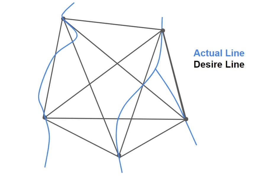
- O&D data is represented by Desire Line.

- Desire lines are the straight line joining origin to destination.
- The width of desire line is proportional to the number of trips in both directions.
- The desire line density map helps to decide the actual desire of the road user with respect to path to be followed between two points.
Pie Chart
O&D studies data can also be represented in the form ‘Pie Chart’ & ‘Contour Lines’.
2.Accident Study
One of the primary goals of traffic engineering is to ensure safe traffic flow. Road accidents cannot be avoided, but they can be significantly minimized with proper traffic engineering. So, it is essential to analyses every individual accident and maintain zone wise accident records.
The Accident Studies’ goals are as follows:
- To study the cause of accident.
- To support proposed designs.
- To figure out how much money you’ve lost due to accidents.
- To analyze the changes required in existing design.
Accidents are caused by a variety of factors:
- Drivers
- Road Design
- Traffic Conditions
- Weather
- Animals
- Road Conditions
- Vehicle Defects
Types of Accident
- When a moving car collides with a parked vehicle
- When two vehicles approaching from different directions collide at a intersection
- Head-on collision of two vehicles approaching from opposite directions
- When a moving vehicle collides with a stationary item such as an electric pole, a tree, or a stiff structure.
Mathematical Analysis of Accident Studies
The following assumptions involved in the analysis of accidents are:
- If skid marks are present, then it is assumed that 100% skid occurs.
- If skid marks are not present then free collision is assumed means no brakes are applied.
According to Newton’s law of collision,
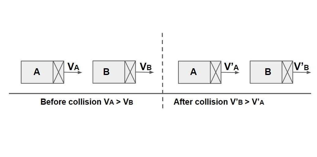
Coefficient of Restitution,
e= \(\frac{\text{Velocity of Separation}}{\text{Velocity of Approach}}\).
e= \(\frac{V_B’-V_A’}{V_B-V_A}\)
Case-1: Elastic Collision
e=1, Velocity of Separation = Velocity of Approach
(VB‘-VA‘)= (VB-VA)
Case-2: Perfectly Plastic Collision
e=0, Velocity of Separation = 0
(VB‘-VA‘)= 0
VB‘-=VA‘
Both velocity will stick & will more together.
Accident Case Study
When A Moving Vehicle Collides With Parked Vehicle
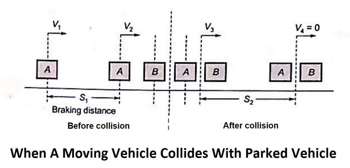 Assumption
- Vehicle ‘A’ applies break before collision.
- Braking efficiency is 100%.
- Collision is perfectly plastic.
| Vehicle A | Vehicle B | |
| initial speed | v1 | 0 |
| speed just before collision | v2 | 0 |
| speed just after collision | v3 | v3 |
| skid before collision | s1 | 0 |
| skid after collision | s2 | s2 |
| mass of vehicle | ma | mb |
| friction coefficient | f | f |
Step-1: Before Collision
ΔKE = work done
\(\frac{1}{2}m_a\cdot v_2^{2}-\frac{1}{2}m_a\cdot v_1^{2}\)=\(-m_a\cdot g\cdot f\cdot s_1\).
\(\frac{v_2^{2}}{2}+gfs_1=\frac{v_1^{2}}{2}\).
\(v_1=\sqrt{v_2^{2}+2gfs_1}\)……(1)
Step-2: At Collision
Momentum just before collision= Momentum just after collision
ma·v2+mb·0= (ma+mb)v3
\(v_2=\frac{m_a+m_b}{m_a}v_3\)……(2)
Step-3: After Collision
ΔKE = work done
\(0-\frac{1}{2}(m_a+m_b)v_3^{2}\)=\(-(m_a+m_b)gfs_2\).
\(v_3=\sqrt{2gfs_2}\)…….(3)
From equation 1, 2 & 3. we will calculate v1, v2, v3.
3.Parking Study
One of the primary issues brought on by increased road traffic is parking. Because no vehicle can move on the road for the entire 24 hours of the day, they must stop or park at different locations for different periods of time. As per IRC the standard dimensions of a car is taken as 5× 2.5 metres and that for a truck is 3.75× 7.5 metres.
Parking facilities may be divided into two types.
- Off Street Parking
- On Street/ Kerb Parking
Off Street Parking
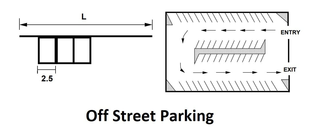
- Off-street parking is given in areas where parking demand is high and kerb parking is not permitted, depending on space availability.
- Vehicles must park away from the kerb in this form of parking.
- The main benefit of this type of parking is that there is no traffic interruption while parking.
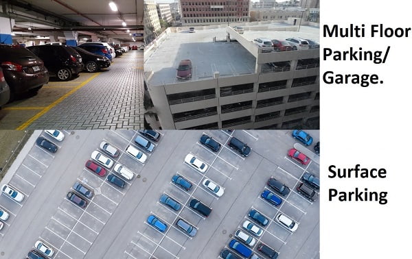
- These are further classified into two.
- Surface Parking
- Multi Floor Parking/ Garage.
On Street/ Kerb Parking
- In this type of parking, vehicles are parked along the kerb which may be designed for parking.
- Different patterns of kerb parking are
- Parallel Parking
- Angle Parking
Parallel Parking
- It requires less road width but the number of vehicles that can be parked per unit length of road is least in this case.
- When kerb parking space and street width are limited, it is preferred.
- Parking and un-parking are more complicated and time consuming in this type of parking.
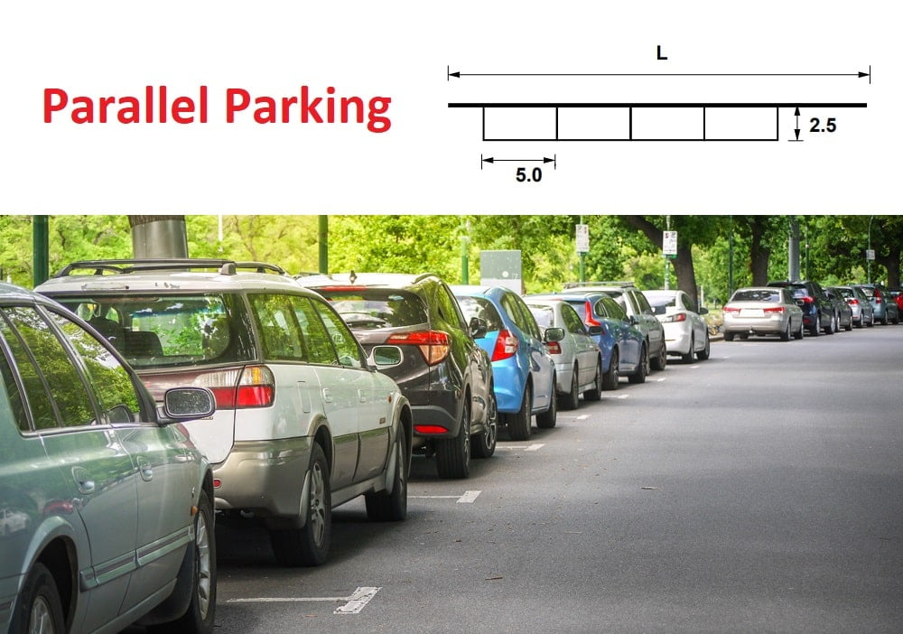
\(N=\frac{L}{5.9}\) (From NPTEL)
\(N=\frac{L}{6.6}\) (From Coaching Book: Made Easy & IES Master Theory Book)
L= Length of kerb
N= Number of parking spaces.
Angle Parking
- In this case vehicles are being parked at an angle ranging from 30°, 45°, 60°, and 90°.
- it is suitable to be provided where availability of road width is more.
- Angle parking accommodates more vehicle per unit length but maximum vehicles can be parked with an angle of 90°.
- 45° angle parking is considered to be the best.
30° Angle Parking
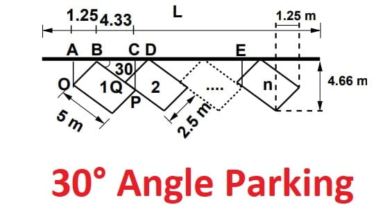
AB = OBsin30◦ = 1.25,
BC = OPcos30◦ = 4.33,
BD = DQcos60◦ = 5,
CD = BD − BC = 5 − 4.33 = 0.67,
AB + BC = 1.25 + 4.33 = 5.58
For N vehicle, L = AC + (N-1)CE =5.58+(N-1)5 =0.58+5N
L = 0.58 + 5N (From NPTEL)
L = 0.85 + 5.1N (From Coaching Book: Made Easy & IES Master Theory Book)
45° Angle Parking
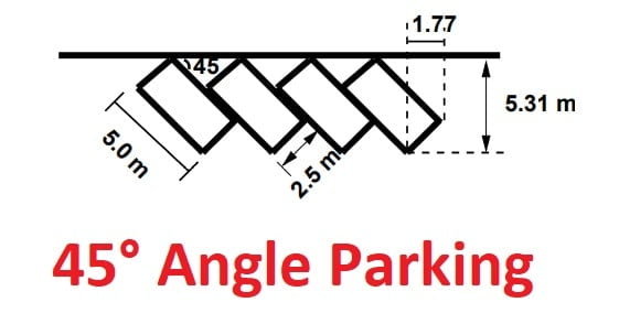
L = 1.77 + 3.54N (From NPTEL)
L = 2 + 3.6N (From Coaching Book: Made Easy & IES Master Theory Book)
60° Angle Parking
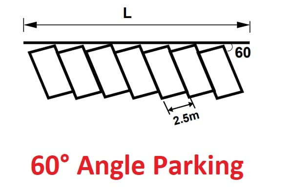 L = 2.16+ 2.89N (From NPTEL)
L = 2 + 2.9N (From Coaching Book: Made Easy & IES Master Theory Book)
90° Angle Parking
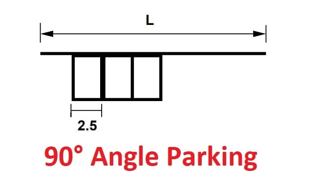 L = 2.5N
Question: Ratio of width of the car parking area required at kerb for 45° parking relative to 60° parking approximately…..
Solution
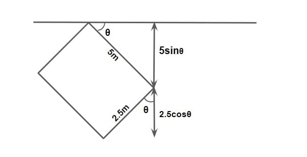
As per IRC, the standard dimension of a car = 5m × 2.5m.
W45 = 5 sin45 + 2.5 cos45 = 5.30
W60 = 5 sin60 + 2.5 cos60 = 5.58
Ratio= \(\frac{W_{45}}{W_{60}} =\frac{5.30}{5.58}\)
Ratio=0.949
Parking statistics
Parking Accumulation
- It is defined as the number of vehicles parked at a given instant of time. Normally this is expressed by accumulation curve. Accumulation curve is the graph obtained by plotting the number of bays occupied with respect to time.
Parking Volume
- Parking volume is the total number of vehicles parked at a given duration of time. This does not account for repetition of vehicles. The actual volume of vehicles entered in the area is recorded.
Parking load
Parking load gives the area under the accumulation curve. It can also be obtained by simply multiplying the number of vehicles occupying the parking area at each time interval with the time interval. It is expressed as vehicle hours.
Average Parking Duration
It is the ratio of total vehicle hours to the number of vehicles parked.
Parking Duration = parking load ÷ parking volume
Parking Turnover
It is the ratio of number of vehicles parked in a duration to the number of parking bays available.
parking turnover = parking volume / No of bays available
This can be expressed as number of vehicles per bay per time duration.
Parking Index
Parking index is also called occupancy or efficiency. It is defined as the ratio of number of bays occupied in a time duration to the total space available. It gives an aggregate measure of how effectively the parking space is utilized.
Parking index can be found out as follows
parking index = \(\frac{\text{parking load}}{\text{ parking capacity}}\times 100\)
Thank you for this notes it helped me prepare for my semester exams