Plane Table Surveying
- Plane table surveying is a graphical method of surveying in which field work and plotting are done simultaneously. It is also known as Plane tabling.
- It is mainly used for small and medium scale mapping (1 : 10000 to 1 : 250,000) where high is not desired.
- It is also used for plotting the topographical maps in the field.
- Here, since plotting and observation are done simultaneously, time required is less .
- No skilled man power or special instrument is required in this case, hence its is economical & less costly than a theodolite survey.
- It is rapid method. Angles are obtained graphically.
- The sighting and plotting are done simultaneously hence there is no chance of missing any detail.
- It is very advantages in areas, where compass survey is not reliable e.g. area affected by magnetic field.
- It is not suitable for, work in a wet climate and in a densely wooded (dense forests) country.
- It does not give very accurate result.
- It is difficult to handle due to its weight.
- Rainy days cannot be utilized for surveying while using a plane table.
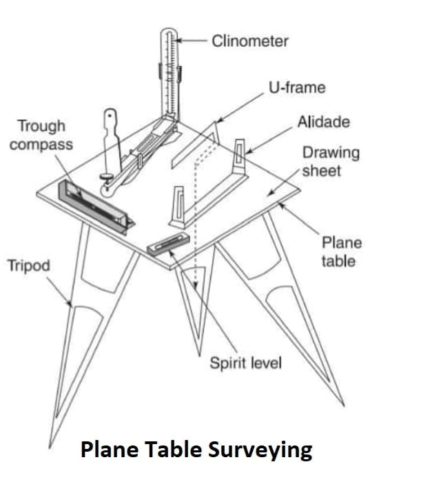
Accessories Used in Plane Table Surveying
- Plane Table Board
- Alidade
- Tripod
- Level Tube/ Spirit Level
- Compass
- Plumbing Fork
Plane Table Board
- Plane table board is wooden drawing board made of well seasoned wood so that counteract the effect of warping and damage due to weathering.
- it mounted on a tripod which can be clamped in any position with the help of wing nut.
- The upper surface is kept smooth.
- Plane tables are available in the following different sizes.
| Designation | Size (mm×mm) |
| B0 | 1500×1000 |
| B1 | 1000×700 |
| B2 | 700×500 |
| B3 | 500×350 |
Alidade (for orientation)
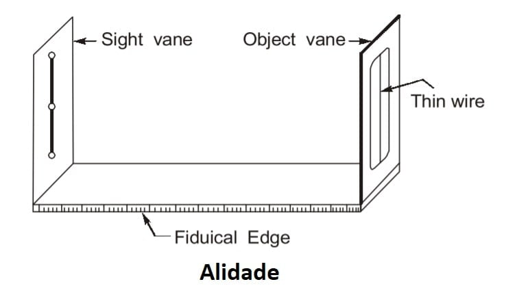
- Alidade is a straight edge ruler used for sighting the objects and drawing lines with object vane and sight vane. Line of sight will be parallel to the fiducial edge.
- It is also used for drawing lines.
Tripod (for stand)
- The plane table is mounted on a tripod stand.
- It can be folded for the transportation.
- It is levelled, rotated about a vertical axis and clamped in position.
Level Tube/ Spirit Level (for leveling)
- Level tubes is required to ensure levelling the table surface.
- The level tube can be place in two perpendicular direction and levelled.
Compass (for orientation)
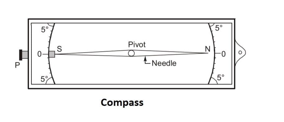
- A magnetic needle in a rectangular box.
- It is used to orient the plane table w.r.t magnetic meridian.
Plumbing Fork (for centering)
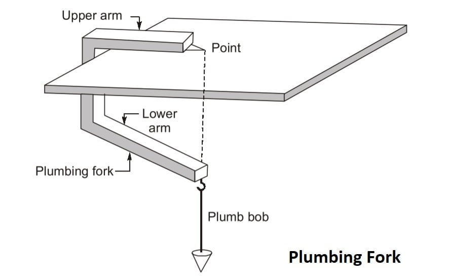
- It is a U-shape metallic frame used for centering the table over the station.
- It can also be used for transferring the point from ground over the table & vice-versa.
Procedure
- Fixing of Plane Table
- Leveling of Plane Table ⇒ Spirit level
- Centering of Plane Table ⇒ Plumbing fork
- Orientation of Plane Table ⇒ Compass or Back sighting
Setting up the Plane Table
Following operations are included in setting up of the plane table.
1.Centering
- It is the operation of bringing the plotted station point exactly over the ground station.
- A plumbing fork is used for checking the centering.
NOTE: Exact centering is important for large scale mapping only. For small scale mapping, an error in centering of about 30 cm is permissible.
2. Levelling
- It is the operation of bringing the plane table in horizontal plane.
- Level the board with the help of a spirit level.
3. Orientation
- It is the operation of keeping the plane table parallel to the position it occupied at first station.
- it can done by following methods
(a) Orientation with a Trough Compass
- It is not suitable to be used in place which are effected by local attraction.
- A trough compass is placed on the top right side corner of the plane table in such a way that the magnetic needle points exactly towards the N-S direction.
- Draw a line along the edge of the compass.
- Shift and set up the plane table on the next station. Place the trough compass along the N S line.
- Rotate the table till the magnetic needle coincides with N-S Fine previously drawn.
- Drawback: This method of orientation is not very accurate.
(b) Orientation by Back-Sighting
- This is the most accurate method of orientation. The plane table is set on a new station and the alidade is placed against the line joining the new station with the preceding station. The table is rotated until the line of sight bisects the previous station.
- To achieve this, let the plane table be shifted from station A to B , and let the line ab has been plotted with the plane table at A. Set up the table on B. place the alidade along the plotted line ba and rotate the table until the line of sight bisects the station A. Clamp the board. The line ba truly represents the line BA on the ground.
(c) Resection
- The method of resection will be discussed later in this chapter in details
Question Which of the following represents the correct order of setting up of plane table.
- Centering, levelling and orientation
- Centering, orientation and levelling
- Levelling, Centering and orientation
- Levelling, orientation and centering
Solution- (A)
Method Of Plane Table Survey
The method of surveying with a plane table include:
- Radiation
- Traversing
- Intersection
- Resection
- Compass Method
- Back Ray Method
- Three Point Problem
- Two Point Problem
1. Radiation Method
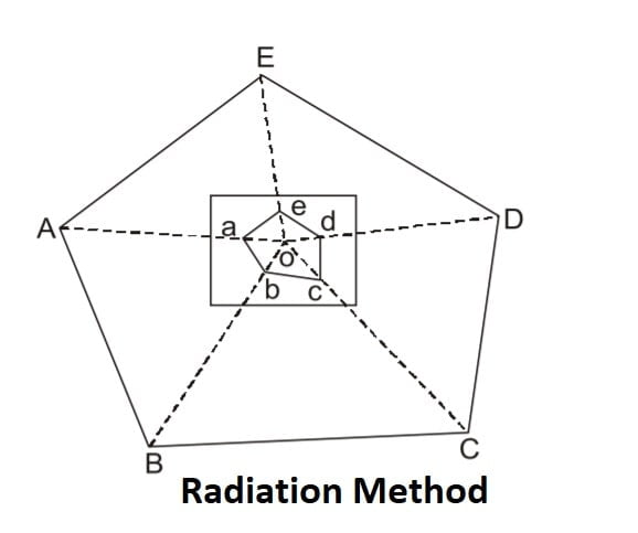
- In this method the instrument is setup at a station and rays are drawn to various points / stations which are to be plotted.
- The distance are cut to a suitable scale after actual measurements.
- This method is suitable only when the area to be surveyed is small all the required station are visible and accessible from the instrument station.
- The scope of this method can be increased if the distance are measured by the help of tacheometer.
2. Traversing Method
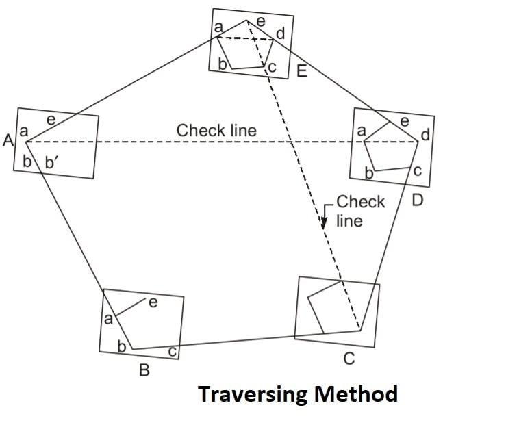
- This method of traversing is same as compass traverse and theodolite traverse.
- A plane table traverse is a very rough type of traverse and is used generally for depicting the topographical details directly on the plane table.
- Traverse consists of a series of straight lines connected together.
- In plane table traversing, the angles are not measured but are in fact plotted directly.
- Plane table traversing is run between the stations whose positions have previously been fixed by some other precise methods like the theodolite traverse or the triangulation.
- The plane table is set successively on the traverse stations and back sight is taken on the preceding station followed by foresight on the following station.
- The measured traverse lines are plotted directly on the paper to some suitable scale.
Note:
- If there are ‘n’ station in closed traverse, then table is to be set on at least ‘n-1’ stations.
- To know the error of closer, setting is to be done for at least ‘n-2’ stations.
3.Intersection Method
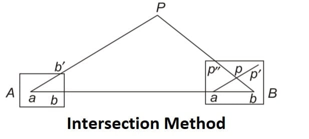
- It is also called as graphical triangulation.
- This method is used when distance point and instrument station is large or cannot be measured accurately.
- The location of object is determined by sighting at the object from two plane table stations which are previously plotted.
- The line joining the two instrument station is termed as Base Line.
- In this method no liner measurement is required except that of base line.
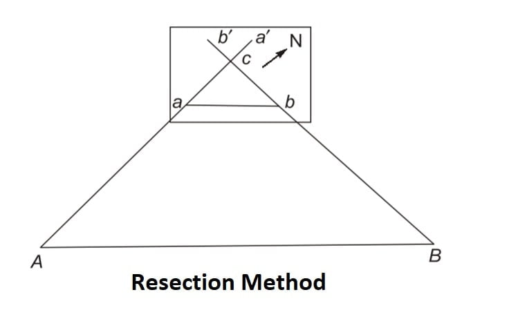
4.Resection Method
 It is a method of orientation employed when the table occupies a position not yet located on the drawing sheet. Therefore, it can be defined as the process of locating the instrument station occupied by the plane table by drawing rays from the stations whose positions have already been plotted on the drawing sheet. The resection of two rays will be the point representing the station to be located, provided the orientation at the station to be plotted is correct, which is seldom achieved. The problem can be solved by any of the methods such as resection after orientation by back ray, by two points, or by three points. These methods are described in the sections to follow.
- This method requires only one linear measurement.
 It is a method of orientation employed when the table occupies a position not yet located on the drawing sheet. Therefore, it can be defined as the process of locating the instrument station occupied by the plane table by drawing rays from the stations whose positions have already been plotted on the drawing sheet. The resection of two rays will be the point representing the station to be located, provided the orientation at the station to be plotted is correct, which is seldom achieved. The problem can be solved by any of the methods such as resection after orientation by back ray, by two points, or by three points. These methods are described in the sections to follow.
Method of Resection
- Compass Method
- Back Ray Method
- Three Point Method
- Two Point Problem
Compass Method of Resection
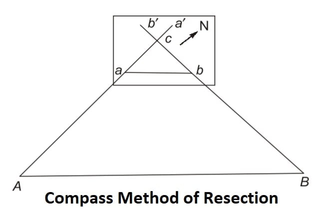
- This method of resection is used for relatively small works where the orientation errors in plane table do not significantly affect the location of plane table.
- This method assumes that the direction of magnetic meridian has been already marked.
- It is assumed that the area is not magnetically disturbed.
The following steps are followed as shown in
- Let C be the instrument station to be plotted over the plan with the help of two visible stations A and B which are already plotted on plan as a &b.
- Set the table at the station C and orient it with compass.
- Clamp the table, pivot the alidade at point ‘a’ & draw the resector toward
- Set up the plane table at station C. Level it and orient it roughly by the judgment of eye.
- Place the trough compass along the meridian line and rotate the plane table until the needle points to zero mark of the scale. Clamp the table at this position.
- Pivot the alidade at a’ and sight the ranging rod at A. Draw a ray aa’ towards A. This ray is called as the resection line or the resector. It is the ray drawn through the plotted position ‘a’ of known station A towards the plane table at C.
- Pivot the alidade on ‘b’ and sight the ranging rod at B. Draw a ray ‘bb” towards B.
- The intersection of the rays ‘aa’ and ‘bb gives the position of station Ci.e. ‘c’ on the paper.
Back Ray Method of Resection
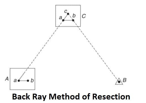
- Let a and b be the plotted positions of the two ground stations A and B. Station C is to be plotted. Set up the table at A, with a above A. Keep the alidade along ab and orient the table so that B is bisected. Pivot the alidade at a, sight C and draw ray ac. Shift the instrument and set it up at C. Place the alidade along ca and rotate the table till it is oriented. With alidade pivoted against b, sight B and draw a back ray. The resection of this ray with the previous ray gives the position of station C as c on the drawing sheet.
Two Point Problem of Resection
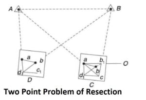
- Let A and B be the two stations plotted as a and b on the drawing sheet. It is required to plot station C, where the plane tabling is to be done.
- Choose an arbitrary station D such that CD is approximately parallel to AB. ∠CAD and ∠CBD should not be very acute, which is the necessary condition for good intersection of points.
- Set up the plane table at D. Orient it approximately by eye judgement such that ab is parallel to AB. Clamp the table.
Pivot the alidade against a, sight A, and draw a back ray. Pivot the alidade against b, sight B, and draw a back ray. The two rays intersect at d₁. - This will not be the correct position of D as the orientation at D is not exact.
- Pivot the alidade against d, and sight C. Draw a ray d,C and fix the position of c, by estimation.
- Shift the table to station C. Set up the table and orient it by back sighting at station D.
- Pivot alidade against a, sight A and draw a back ray resecting the line d₁c, in c.
- Pivot the alidade at c and sight B. Draw a ray to B. If the ray passes through the plotted point b, the orientation of the table is correct and c is the correct position of C. Whereas, if this ray cuts the previously plotted line dib at some other point, say b₁, then the position c is not the correct position of C. To eliminate this error the table must be rotated by the ∠bab. To do this a ranging rod O is fixed, in line with ab, far away from the plane table.
- The alidade is kept along ab, and O is bisected.
- The alidade is kept along ab and the table is rotated till the ranging rod at 0 is bisected. It is oriented now. The table is then clamped.
- With alidade touching a sight A and draw a back ray to C. Then, with alidade touching b, sight B and draw a back ray to C. The resection of these two rays gives the position of C.
Three Point Problem of Resection
Three point consist of locating the position of instrument station on plan/ drawing sheet with the help of observation of three well-defined point whose position have been already plotted on the plan.
It can done by following method:
- Mechanical Method or Tracing Paper
- Graphical Method
- Trial and Error Method or Lehmann’s Method
Note: These methods are not important as exam point of view. so these methods are not discuss here.
First process of setting the plane table is 1.levelling, 2.centring, 3.orientation
Shortcut(LCO)