Rapidly Varied Flow
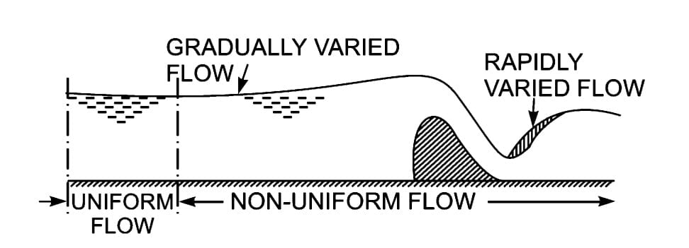
- In Rapidly Varied Flow (R.V.F), a sudden change of depth occurs at a particular point of a channel and the change from one depth to another takes place at a distance of very short length.
- Streamlines in Rapidly Varied Flow (R.VF) have very large curvature. Most of the time and about change in curvature breaks the flow profile and this results in a high state of turbulence causing considerable loss of energy.
- Hydraulic jump is the best example of RVF.
- Pressure distribution is non-hydrostatic due to the huge curvature of flow.

Hydraulic Jump
When the flow condition changes from supercritical (Fr >1) to subcritical (Fr <1), the result is an abrupt rise of water accompanied by turbulent rollers, this local phenomenon is called hydraulic jump or standing wave.
The change in flow regime takes place over a relatively short reach of a channel, so it is a local phenomenon, therefore, boundary friction is relatively small and in many cases insignificant.
A hydraulic jump will form when water moving at a supercritical velocity in a relatively shallow stream strikes water having large depth and subcritical velocity. For example:
- Downstream of the sluice gate.
- At the bottom of spillway
- When the steep channel changes to a flat channel.
- Downstream of narrow channel
- Irrigation canal falls
Applications of Hydraulic Jump
- To aerate polluted stream.
- For desalination of seawater.
- To mix chemicals used for water purification or wastewater treatment.
- As an energy dissipator, to dissipate the excess energy of flowing water downstream of hydraulic structures and the present scouring downstream.
- To raise the water level on the downstream side of a metering flume and thus maintain high water.
Analysis of Hydraulic Jump
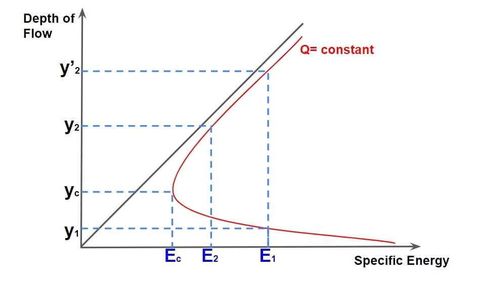
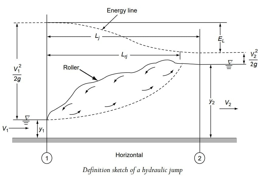
⇒ During hydraulic jump the supercritical flow streams jump to meet their alternate depth, but while doing so it generates considerable disturbance in form of large-scale eddies & reverse flow roller, due to this jump falls short of attaining its alternate depth.
⇒ Thus the resulting depths y1 and y2 are called sequent depth or conjugate depth.
Note:
- Here y1 and y’2 are alternate depths i.e depth with a specific energy. And y1 and y2 are sequent/ conjugate depth. i.e two depths of hydraulic jump with the same specific force.
- Toe of Jump: Section 1-1, where the incoming supercritical stream undergoes an abrupt rise in the depth forming the commencement of jump is called Toe of jump.
- End of Jump: It is the point at which the roller formation terminates (section 2-2) and the water surface is leveled.
- Length of Jump: The distance between the Toe of the jump (section 1-1) and the end of the jump (section 2-2) is called the length of jump.
Momentum Equation for the Hydraulic Jump
Due to the appreciable energy loss associated with the hydraulic jump, and the nature of which is difficult to estimate, the application of the energy equation at the toe & end of jump does not provide the result of the analysis.
In such a situation the momentum equation comes handy with the following assumption.
- The portion of hydraulic jump is considered as CV (control volume) & is assumed that before & after jump flow is having hydrostatic pressure distribution.
- The length of the jump is small, such that losses due to friction is neglected.
- The channel bed is horizontal or the bed slope is gentle that the weight component of the water mass comprising the jump is negligibly small.
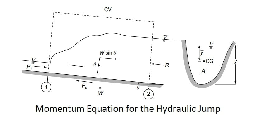
A control volume enclosing the jump as shown by dashed lines in the figure is selected. The flow is considered to be steady.
Applying the linear momentum equation in the longitudinal direction to the control volume,
P1 + W·sinθ -P2 -Fs =M2 – M1
where P1 = pressure force at the control surface at Section 1= γ·A 1 ·\(\bar{y_1}\) ·cosθ by assuming hydrostatic pressure distribution, where \(\bar{y_1}\) = depth of the centroid of the area below the water surface.
P2 = pressure force at the control surface at Section 2= γ·A 2 ·\(\bar{y_2}\) ·cosθ by assuming hydrostatic pressure distribution, where \(\bar{y_2}\) = depth of the centroid of the area below the water surface. (Note that P2= γ A\(\bar{y_2}\) if θ is small.)
Fs = shear force on the control surface adjacent to the channel boundary.
W sin θ = longitudinal component of the weight of water contained in the control volume.
M1 = momentum flux in the longitudinal direction going out through the control surface = β2 ρ2 Qv2 .
M1 = momentum flux in the longitudinal direction going out through the control surface = β1 ρ1 Qv1 .
As per assumptions considered,
Wsinθ = 0
Fs=0
α,β= 1
So momentum equation become
P1 -P2 =M2 – M1
P1 +M1 =M2 + P2
\(\frac{P_1 +M_1}{\gamma }=\frac{P_2 +M_2}{\gamma }\)
Here specific force is constant under frictionless & horizontal surface.
specific force= constant
\(\frac{P +M}{\gamma }\)= constant
\(\frac{\gamma \cdot A\cdot \bar{y}+\frac{\rho Q^{2}}{A}}{\gamma }\)= constant
\(A\cdot \bar{y}+\frac{Q^{2}}{gA}\)= constant
Hydraulic Jump in A Horizontal Rectangular Channel
(A) Sequent Depth Ratio:
Consider a horizontal, frictionless, and rectangular channel. the momentum equation can be written in the form
\(A\cdot \bar{y}+\frac{Q^{2}}{gA}\)= constant
\(By\cdot \frac{y}{2}+\frac{Q^{2}}{gBy}\)= constant
\(\frac{y^{2}}{2}+\frac{Q^{2}}{gB^{2}y}\)= constant
\(\frac{y^{2}}{2}+\frac{q^{2}}{gy}\)= constant
\(\frac{y_1^{2}}{2}+\frac{q^{2}}{gy_1}\)=\(\frac{y_2^{2}}{2}+\frac{q^{2}}{gy_2}\)
\(\frac{q^{2}}{g}[\frac{1}{y_1}-\frac{1}{y_2}]=\frac{y_2^{2}-y_1^{2}}{2}\)
\(\frac{2q^{2}}{g}[\frac{y_2-y_1}{y_2\cdot y_1}]=(y_2- y_1)(y_2+ y_1)\)
\(\frac{2q^{2}}{g}=(y_2\cdot y_1)(y_2+ y_1)\)
\(F_r=\frac{v}{\sqrt{g\frac{A}{T}}}\).
\(F_r=\frac{v}{\sqrt{gy}}\).
\(F_r=\frac{Q}{A\sqrt{gy}}\).
\(F_r=\frac{Q}{By\sqrt{gy}}\).
\(F_r=\frac{q}{y\sqrt{gy}}\).
\(F_{r1}^{2}=\frac{q^{2}}{gy_1^{3}}\),
\(F_{r2}^{2}=\frac{q^{2}}{gy_2^{3}}\).
\(\frac{q^{2}}{g}=F_{r1}^{2}\cdot y_1^{3}=F_{r2}^{2}\cdot y_2^{3}\).
\(\frac{2q^{2}}{g}=(y_2\cdot y_1)(y_2+ y_1)\)
\(2\cdot F_{r1}^{2}\cdot y_1^{3}=2\cdot F_{r2}^{2}\cdot y_2^{3}=(y_2\cdot y_1)(y_2+ y_1)\)
\(2\cdot F_{r1}^{2}\cdot y_1^{3}=(y_2\cdot y_1)(y_2+ y_1)\).
\(2\cdot F_{r1}^{2}=\frac{(y_2\cdot y_1)}{ y_1^{3}}(y_2+ y_1)\).
\(2\cdot F_{r1}^{2}=\frac{y_2}{ y_1^{2}}(y_2+ y_1)\).
\(2\cdot F_{r1}^{2}=\frac{y_2}{ y_1}+\frac{y_2^{2}}{y_1^{2}}\).
\(\frac{y_2^{2}}{y_1^{2}}+\frac{y_2}{ y_1}-2\cdot F_{r1}^{2}=0\).
| \(\frac{y_2}{ y_1}=\frac{-1\pm \sqrt{1+8F_{r1}^{2}}}{2}\) |
similarly
| \(\frac{y_1}{ y_2}=\frac{-1\pm \sqrt{1+8F_{r2}^{2}}}{2}\) |
Note:
- The above equation is also termed as ‘BELANGER MOMENTUM EQUATION’.
- For high values of F1, say F1 > 8.0, Eq. can be approximated for purposes of quick estimation of the sequent depth ratio as y2/ y1 ≈ 1.41F1
- Above formula is for rectangular, horizontal, and frictionless channels and if friction is not neglected y2 actual will be less than y2 calculated from the above formula.
(B) Energy Loss
The energy loss EL in the jump is obtained by the energy equation applied to Sections 1 and 2 as
EL = E1 −E2
\(E_L=(y_1+\frac{q^{2}}{2g\cdot y_1^{2}})-(y_2+\frac{q^{2}}{2g\cdot y_2^{2}})\).
\(E_L=(y_1 -y_2) +\frac{q^{2}}{2g}[\frac{1}{y_1^{2}}-\frac{1}{y_2^{2}}]\).
\(E_L=(y_1 -y_2) +\frac{q^{2}}{2g}[\frac{y_2^{2}-y_1^{2}}{y_1^{2}y_1^{2}}]\).
∴\(\frac{2q^{2}}{g}=(y_2\cdot y_1)(y_2+ y_1)\).
\(E_L=(y_1 -y_2) +\frac{y_1y_2(y_1+y_2)}{4}[\frac{y_2^{2}-y_1^{2}}{y_1^{2}y_1^{2}}]\).
\(E_L=(y_1 -y_2) +\frac{(y_1+y_2)(y_2^{2}-y_1^{2})}{4y_1y_2}\).
\(E_L= \frac{(y_1 -y_2)4y_1y_2+(y_1+y_2)(y_2^{2}-y_1^{2})}{4y_1y_2}\).
\(E_L= \frac{4y_1^{2}y_2-4y_1y_2^{2}+y_1y_2^{2}-y_1^{3}+y_2^{3}-y_1^{2}y_2}{4y_1y_2}\).
\(E_L= \frac{y_2^{3}-y_1^{3}+3y_1^{2}y_2-3y_1y_2^{2}}{4y_1y_2}\).
∴(a-b)3=a3-b3+3ab2-3a2b
| \(E_L= \frac{(y_2-y_1)^{3}}{4y_1y_2}\) |
Note: Applicable for the horizontal rectangular channel.
(C) Relative Energy Loss
Relative Energy Loss = \(\frac{E_L}{E_1}\times 100\)%
(D) Efficiency of Jump
It is defined as the ratio of the energy of jump after & before its formation.
Efficiency of Jump (ηjump) = \(\frac{E_2}{E_1}\times 100\)%
Efficiency of Jump (ηjump)= 1- Relative Energy Loss
(E) Height of Jump
It is defined difference in the level of water after & before its formation.
Height of Jump (Hj) =y2 – y1
| Relative Initial Depth = \(\frac{y_1}{E_1}\) |
| Relative sequent Depth = \(\frac{y_2}{E_1}\) |
(F) Length of Jump
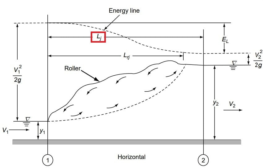
Length of jump (Lj) is the horizontal distance between the toe of the jump to a section where the water surface level starts to take off and the end of the jump.
The length of jump is required while selecting the apron length and the height of the side walls of the stilling basin.
Experimentally it is found that in a horizontal channel.
If F1<5 \(\frac{L_j}{y_2}=f(F_1)\)
If F1>5 \(\frac{L_j}{y_2}=6.1\)
Note: Experimentally length of jump is also equal to
Lj = 6.9(y2-y1)
Lj = 6.9×Hj
Classification of Jumps
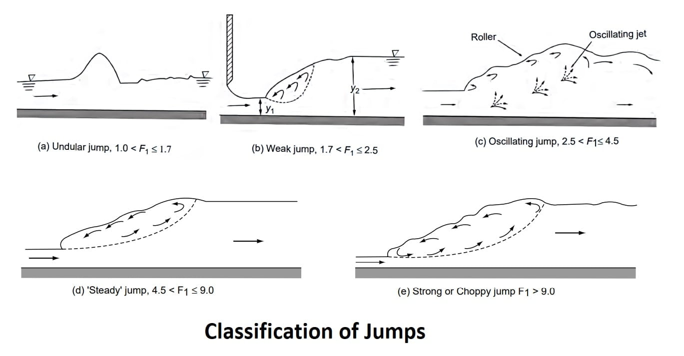
The hydraulic jumps in horizontal rectangular channels are classified into five categories based on the Froude number F1 of the supercritical flow.
It should be noted that the Froude number of incoming flow should be always greater than 1 to occur.
(i) Undular Jump (1.0 < F1 ≤ 1.7)
The water surface is undulating with a very small ripple on the surface. The sequent-depth ratio is very small and EL /E1 is practically zero. A typical undular jump is shown in Fig: (a).
(ii) Weak Jump (1.7 < F1 ≤ 2.5)
The surface roller makes its appearance at F1 ≈ 1.7 and gradually increases in intensity towards the end of this range, i.e. F1 ≈ 2.5. The energy dissipation is very small, is EL/E1 about 5 percent at F1 = 1.7 and 18 percent at F1 = 2.5. The water surface is smooth after the jump Fig.(b).
(iii) Oscillating Jump (2.5 < F1 ≤ 4.5)
This category of jump is characterized by an instability of the high-velocity flow in the jump which oscillates randomly between the bed and the surface. EL/E1 = 18-45%. These oscillations produce large surface waves that travel considerable distances downstream Fig.(c).
(iv) Steady Jump (4.5 < F1 ≤ 9.0)
In this range of Froude numbers, the jump is well-established, and the roller and jump action is fully developed to cause appreciable energy loss Fig.(d). The relative energy loss EL/ E1 ranges from 45 percent to 70 percent in this, class of jump. The ‘steady jump’ is least sensitive in terms of the toe position to small fluctuations in the tailwater elevation.
(v) Strong or Choppy Jump (F1>9.0)
In this class of jump, the water surface is very rough and choppy. The water surface downstream of the jump is also rough and wavy Fig.(e). The sequent-depth ratio is large and the energy dissipation is very efficient with EL / E1 values greater than 70 percent.
Velocity Profile For Hydraulic Jump
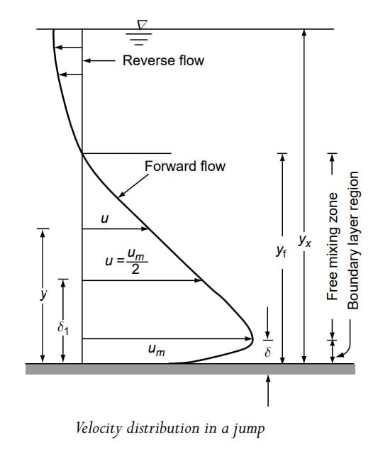
It is observed that the velocity profile has two district portions (a) a forward flow in the lower main body. (b) a negative reverse flow at the top.
The forward velocity profile has zero velocity at the bed, the maximum velocity at a distance of “δ” & then it gradually decreases to zero at height of “iff” above the bed.
Here
0<y<δ is called the boundary layer.
δ<y<yf is called a free mixing zone.
Jumps in Horizontal Non-rectangular Channels
If the side walls of a channel are not vertical, e.g. in the case of a trapezoidal channel, the flow in a jump will involve lateral expansion of the stream in addition to an increase in depth.
The cross-sectional areas are not linear functions of the depth of flow, and computation of jump properties is comparatively difficult.
Specific force can be used to find the sequent depth in this case for a given discharge, as follows
\(\frac{P +M}{\gamma }\)= constant
\(\frac{\gamma \cdot A\cdot \bar{y}+\frac{\rho Q^{2}}{A}}{\gamma }\)= constant
| \(A\cdot \bar{y}+\frac{Q^{2}}{gA}\)= constant |
\(A_1\cdot \bar{y_1}+\frac{Q^{2}}{gA_1}=A_2\cdot \bar{y_2}+\frac{Q^{2}}{gA_2}\)
\(A_2\cdot \bar{y_2}-A_1\cdot \bar{y_1}=\frac{Q^{2}}{gA_1}-\frac{Q^{2}}{gA_2}\).
\(A_1\cdot \bar{y_1}(\frac{A_2\cdot \bar{y_2}}{A_1\cdot \bar{y_1}}-1)=\frac{Q^{2}}{g}(\frac{1}{A_1}-\frac{1}{A_2})\).
\(A_1\cdot \bar{y_1}(\frac{A_2\cdot \bar{y_2}}{A_1\cdot \bar{y_1}}-1)=\frac{Q^{2}}{g}(\frac{A_2-A_1}{A_2A_1})\).
\((\frac{A_2\cdot \bar{y_2}}{A_1\cdot \bar{y_1}}-1)=\frac{Q^{2}}{A_1^{2}\cdot \bar{y_1}\cdot g}(\frac{A_2-A_1}{A_2})\)…. ….(1)
We know that
\(F_1=\frac{v_1}{\sqrt{g\cdot A_1/T_1}}\)
squaring both sides
\(F_1^{2}=\frac{v_1^{2}}{g\cdot A_1/T_1}\)
Q=Av
\(F_1^{2}=\frac{(Q/A_1)^{2}}{g\cdot A_1/T_1}\).
\(\frac{F_1^{2}g\cdot A_1}{T_1}=\frac{Q^{2}}{A_1^{2}}\).
\(\frac{F_1^{2}g\cdot A_1^{3}}{T_1}=Q^{2}\).
put the value of Q2 in the above equation….(1)
\((\frac{A_2\cdot \bar{y_2}}{A_1\cdot \bar{y_1}}-1)=\frac{F_1^{2}g\cdot A_1^{3}}{A_1^{2}\cdot \bar{y_1}\cdot g\cdot T_1}(\frac{A_2-A_1}{A_2})\).
\((\frac{A_2\cdot \bar{y_2}}{A_1\cdot \bar{y_1}}-1)=\frac{F_1^{2}\cdot A_1}{\bar{y_1}\cdot T_1}(\frac{A_2-A_1}{A_2})\).
| \((\frac{A_2\cdot \bar{y_2}}{A_1\cdot \bar{y_1}}-1)=F_1^{2}(\frac{A_1/T_1}{\bar{y_1} })(\frac{A_2-A_1}{A_2})\). |
The energy loss EL due to a jump in a non-rectangular horizontal channel is
| \(E_L=E_1-E_2=(y_1-y_2)+\frac{Q^{2}}{2g} (\frac{1}{A_1^{2}}-\frac{1}{A_2^{2}})\). |
Jumps on a Sloping Floor
The general momentum equation describes the scenario when a hydraulic jump occurs in a channel with a sloping floor. There are too many unknown terms in relation to the number of available equations, therefore solving the momentum equation is impossible until extra information is supplied.
Even if the simplified situation of a rectangular frictionless (Fs =0) channel is considered, the term W sin θ representing the longitudinal component of the weight of the water in the jump poses a problem as an unknown quantity.
This is because W sin θ involves the length and profile of the jump, information about which can be obtained only through experimental observations. As such, even though many attempts have been made to obtain the sequent-depth ratio through the momentum equation, no satisfactory general solution is available so far.
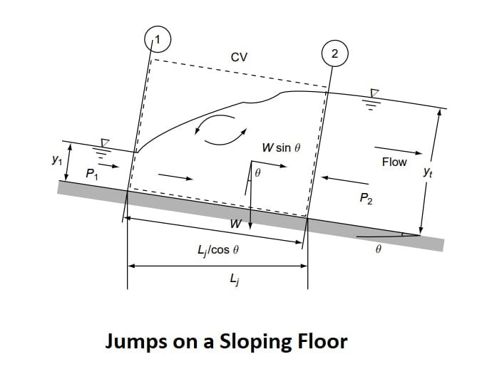
The general momentum equation
P1 + W·sinθ -P2 -Fs =M2 – M1
P1 + W·sinθ -P2 =M2 – M1
\(\frac{P_1+M_1}{\gamma }+\frac{Wsin\theta }{\gamma }=\frac{P_2+M_2}{\gamma }\)
Specific Force ≠ Constant
The length of jump on the sloping floor is longer than the corresponding length on the horizontal floor.
The relative energy loss (EL/E1) decreases with increase in the value of θ slope.
Energy Dissipation
Because of the large amount of energy lost during the jump, has led to its adoption as a part of the energy -dissipator system below a hydraulic structure.
Stilling basin is the downstream portion of the hydraulic structure where the energy dissipation is intentionally allowed to occur such that outgoing stream can be safely discharged into the channel below.
The function of stilling basin is to provide a stable, good jump with high energy dissipation.
Stilling basin is a fully paved section and more additional units such as baffle blocks, chute blocks, and End sills.
Due to the provisions of chute blocks, Baffle blocks. The length of jump and tailwater depth required reduces as compared to an unaided jump.
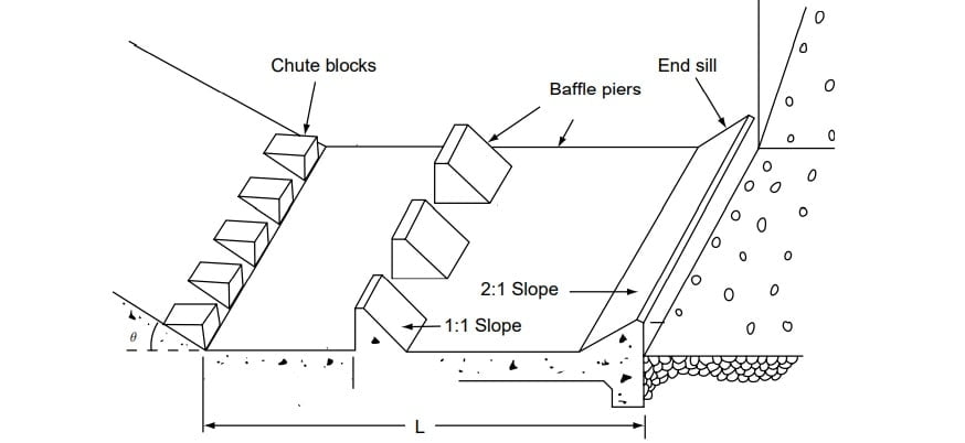
Note:
Chute Blocks- It is used for splitting and aeration of flow.
Baffle Blocks- These provide additional resistance to flow.
End Sill – It helps in lifting the outgoing stream into a trajectory hence avoiding wear & tear, and scouring of d/s side.
Location Of Jump
⇒ Tail water depth plays a important role in jump formation.
⇒ The depth downstream of a hydraulic structure, such as a sluice gate, controlled by the downstream channel or local control is called as tail water depth.
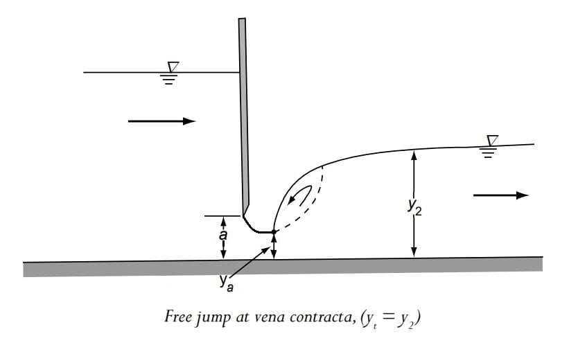
⇒ Consider a flow from a sluice gate of opening ‘a’. The depth of flow at vena contracta is ya. Let the tail water depth be yt.
Depending on values of y2, and yt, following types of jump are identified.
1. yt =y₂ ⇒Free Hydraulic Jump will form at Vena contracta.
2. yt < y₂ ⇒Free Repelled jump
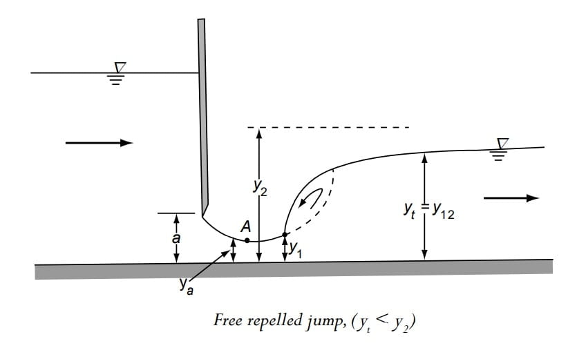
- When tail water depth is less than y2, then the jump is repelled downstream of vena contracta, The jump well start forming at the location where the depth is y’1 (Conjugate depth of yt)
\(\frac{{y_1}’}{y_t}=\frac{-1+\sqrt{1+8F_t^{2}}}{2}\)
3. yt > y2 Submerged or Drowned Jump.
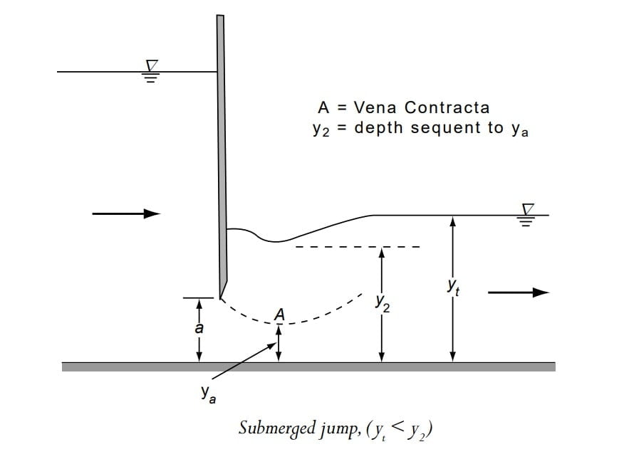
- Energy loss in submerged jump is less.
Question: A sluice gate in a 3.0-m wide rectangular, horizontal channel releases a discharge of 18.0 m3/s. The gate opening is 0.67 m and the coefficient of contraction can be assumed to be 0.6. Examine the type of hydraulic jump formed when the tailwater is (i) 3.60 m (ii) 5.00 m, and (iii) 4.09 m
Solution:
ya = depth at vena contracta = a×Cc = 0.67 × 0.6 = 0.40 m
Va= 18.0 / (3.0 × 0.4) =15.0 m /s
Fa = Froude number at vena contracta = V/(g ya)½
\(F_a=\frac{15}{\sqrt{9.81\times 0.4}}=7.573\)
If y2 = Sequent depth required for a jump at vena contracta
\(\frac{y_2}{y_a}=\frac{-1+\sqrt{1+8F_a^{2}}}{2}\).
\(\frac{y_2}{y_a}=\frac{-1+\sqrt{1+8F_a^{2}}}{2}\).
\(\frac{y_2}{0.40}=\frac{-1+\sqrt{1+8\times (7.573)^{2}}}{2}\).
y2 = 10.22 × 0.40 = 4.09 m
1. When the tailwater depth yt = 3.60 m,
Since yt < y2, a free repelled jump will form.
\(V_t=\frac{18}{3\times 3.60}=1.667m/s\)
\(F_t=\frac{1.667}{\sqrt{9.81\times 3.60}}=0.281\)
The depth at the toe of this repelled jump y1 is given by
\(\frac{y_1}{y_t}=\frac{-1+\sqrt{1+8F_t^{2}}}{2}\).
\(\frac{y_1}{3.60}=\frac{-1+\sqrt{1+8\times (0.281)^{2}}}{2}=0.1387\).
y1 = 0.50 m
An M3 curve will extend from Section A ( ya= 0.40 m) to Section 1 ( y1 = 0.50 m).
2. When the tailwater depth yt = 5.0 m.
Since yt > y2, a submerged jump will occur.
3. When yt = 4.09, yt = y 2 and a free jump will occur at Section 1 with yt= ya = 0.40 m.
it is very interesting clear. Thank you for your effort.
Interesting