Design of Vertical Alignment
Generally Highway is aligned to follow the natural topography keeping in view the drainage and other design consideration.
Note: This topic is part of the second chapter of Highway Engineering. I suggest reading this topic in the context of the complete chapter: Geometric Design of Highway. If you want to read the entire Highway Engineering, click here: Highway Engineering.
The vertical alignment of a highway affects:
Acceleration & Deceleration
Operational cost of vehicle
Sight distance
Vehicle speed
The vertical alignment consist of two element:
1. Gradient | 2. Vertical curve |
Gradient:
It is designed a change in elevation/height of road along the length or maybe defined as rise or fall along the length of road with respect to horizontal.
Slope due to gradual rise or gradual fall in the direction of vehicle movement is called gradient.
If it is gradual rise then the slope is called ascending /rising /positive gradient.
If it is a gradual fall then the slope is called descending/ falling/negative gradient.
It can be represented as follows:
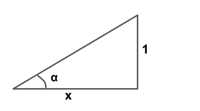
- 1 in x (1 vertical to x horizontal)
- \(\frac{1}{x}\times 100%\)
- tanα
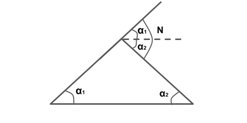
Note: The angle which measures change in direction at the intersection of two grades is called as deviation angle.

N= α1+α2
or N=α1-(-α2)
Type of Gradients:
Gradients are divided into following types.
- Rulling Gradient
- Limiting Gradient
- Exceptional Gradient
- Minimum Gradient
Ruling Gradient:
It is the maximum gradient within which designer wants to design the vertical profile of the road, hence it is also known as design gradients. It depends upon topography, length of the grade, design speed, pulling power of vehicle and presence of horizontal curves.
Limiting Gradient:
It is steeper than ruling gradient and it is provided only when there is an enormous increase of cost of construction with ruling gradient. On rolling and hilly terrain, limiting gradient may be frequently adopted but the length of limiting gradient stretch should be restricted.
Exceptional Gradient:
It is steeper than ruling gradient and limiting gradient and provided only, if the situation is unavoidable. Length of exceptional gradient stitch should not be more than 100 m.

Minimum Gradient:
It is provided along the length of road for drainage point of view. Minimum gradient for cement concrete drain is 1 in 500.
As per IRC minimum gradient is as follows:
| Concrete drainage | 1/500 |
| Kutcha open drainage / Soil drainage | 1/ 200 |
Note: Depending upon the type of soil it can be taken up to 1/100.

Steeper ⇒ EG>LG>RG>MG
Note: Grade Compensation at Horizontal Curves
When there is a horizontal curve in addition to gradient then there will be increased resistance to traction due to both curve and gradient. Therefore it is necessary to reduction in gradient at horizontal curve.
This reduction in gradient at the horizontal curve is termed as “Gradient Compensation“, which is given by
GC%=\(\frac{30+R}{R}\)
R= Radius of horizontal curve
Grade compensation as taken is minimum of \(\frac{30+R}{R}\)% or \(\frac{75}{R}\)%, where ‘R’ is the radius of curve in metres.
Compensated gradient =Gradient-Grade compensation
NOTE:
According to IRC grade compensation is not necessary for the gradient flatter than 4%.hence it is not being provided beyond (less than) 4%.
